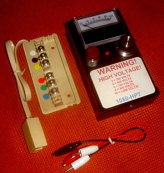
 The 1080HTP performs a variety of high-pot tests on telephone lines, AC power lines, intercom lines and any other wire pairs.
It generates up to 1,000 volts DC at 1+ mA
to test for leakage caused by semiconductors and other components normally used in wiretaps and room audio and data transmitters.
The 1080HTP performs a variety of high-pot tests on telephone lines, AC power lines, intercom lines and any other wire pairs.
It generates up to 1,000 volts DC at 1+ mA
to test for leakage caused by semiconductors and other components normally used in wiretaps and room audio and data transmitters.The unit detects back-to-back zener diodes, SCRs, TRIACS, DIACs, sidactors, thyristors, transistors, TVSs, varistors, gas discharge tubes (including neon), resistors and capacitors. Some of these devices have breakdown voltages of up to 700 volts and capacitors can measure in the thousands of volts.
OPERATION:
TELEPHONE SYSTEMS
 When high-potting ANY wire pair it is imperative that both ends of the
pair are free of known components or equipment. Once the operator is sure that no
equipment is on the wire pair the telephone modular plug may be plugged into the six wire terminal block. The red jack on the 1080HTP is positive(+) with the
YELLOW
polarity switch
to the right (remember, red right) and the black jack is negative (-).
Insert the test leads into these jacks. Connect the one lead to the red terminal on the block (it is clipped onto the copper portion of the lead that runs
from the
screw to the terminal block itself). Connect the other lead to the green terminal. Rotate the voltage control knob fully counterclockwise. With hands clear
of any wires, press
the RED power button. Slowly advance the voltage control. If the meter immediately indicates current flow it shows that the wire is
not free of a foreign device. Again check the wire pair. If the telephone line is totally clear it should be possible to advance the control to the full 1,000 volts.
Release the RED
button and rotate the voltage control to zero.
Place the YELLOWpolarity switch in the left position, press the RED button and advance the voltage to maximum.
Release the RED button. While closely observing the meter throw the polarity switch to the opposite position.
Any pronounced "kick" in the meter indicates that a capacitor is connected to the line. This test will detect capacitors as small as .005 microfarads.
Check the yellow and black wire in both polarities. Test for a capacitor.
Check the blue and white wires in both polarities. Test for a capicitor. Check every pair combination by connecting
one clip to the white terminal and move the other clip in sequence to the black, yellow, red, green and blue terminals. Move the clip that was connected to the white terminal
to the black terminal and use the other clip to test the yellow, red, green and blue terminals. Move the red clip in sequence until all
combinations are tested each time testing for a capacitor. Note, the terminal block is a six wire block.
If testing a four wire modular plug, use only the middle four colors (red, green, yellow and black).
When high-potting ANY wire pair it is imperative that both ends of the
pair are free of known components or equipment. Once the operator is sure that no
equipment is on the wire pair the telephone modular plug may be plugged into the six wire terminal block. The red jack on the 1080HTP is positive(+) with the
YELLOW
polarity switch
to the right (remember, red right) and the black jack is negative (-).
Insert the test leads into these jacks. Connect the one lead to the red terminal on the block (it is clipped onto the copper portion of the lead that runs
from the
screw to the terminal block itself). Connect the other lead to the green terminal. Rotate the voltage control knob fully counterclockwise. With hands clear
of any wires, press
the RED power button. Slowly advance the voltage control. If the meter immediately indicates current flow it shows that the wire is
not free of a foreign device. Again check the wire pair. If the telephone line is totally clear it should be possible to advance the control to the full 1,000 volts.
Release the RED
button and rotate the voltage control to zero.
Place the YELLOWpolarity switch in the left position, press the RED button and advance the voltage to maximum.
Release the RED button. While closely observing the meter throw the polarity switch to the opposite position.
Any pronounced "kick" in the meter indicates that a capacitor is connected to the line. This test will detect capacitors as small as .005 microfarads.
Check the yellow and black wire in both polarities. Test for a capacitor.
Check the blue and white wires in both polarities. Test for a capicitor. Check every pair combination by connecting
one clip to the white terminal and move the other clip in sequence to the black, yellow, red, green and blue terminals. Move the clip that was connected to the white terminal
to the black terminal and use the other clip to test the yellow, red, green and blue terminals. Move the red clip in sequence until all
combinations are tested each time testing for a capacitor. Note, the terminal block is a six wire block.
If testing a four wire modular plug, use only the middle four colors (red, green, yellow and black).
AC POWER LINES INCLUDING APPLIANCES:
Unlike telephone lines, the AC power line is accessible at many points, normally at the AC outlets. It is difficult, but not impossible,
to
clear the line of all appliances and accessories and then test the line. If the line can be cleared the power must be removed by throwing the circuit breaker or removing
the fuse.
Appliances, such as incandescent lamps, may, after removing the bulb, be tested individually. Always check for capacitance. This is particularly important on AC lines.
Clocks, instant on TVs or similar devices may not be tested. They
require visual
inspection.
7/14