WIRE AND DEVICE LOCATOR
|
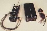
The 2052WL multipurpose detection system identifies and locates all types of radio frequency (RF) fields and hidden wires. The system consists of the 2052WLR (WLR) detector, rod antenna, antenna extension rods, detector module, dynamic earphone, 2052WLT (WLT) wide-band signal generator and two wire antennas. A rugged foam fitted attache case houses all components of the system. THE 2052WLR DETECTOR:
The WLR is a highly sensitive RF detector operating from the
low kilohertz (KHz) range to tens of gigahertz (GHz). The PHONES
output supplies either detected amplitude modulated audio or a tone
proportional to signal strength. With the TONE/AUDIO switch in the
AUDIO position the operator hears demodulated audio and can often
separate the usually stronger signals like AM and TV broadcast
stations from desired signals. The TONE position assists in quick
and accurate location of both the signal from the WLT and
unmodulated or narrow and wide-band FM signals. The tone changes
pitch in proportion to relative signal strength.
The WLR portion of the system includes two different types of
detectors. Quick examination of objects and persons, comparison of
antenna effective radiated power (ERP), testing of transmitters,
monitoring of relative RF field strength in a room, etc. are done
with the rod antenna plugged directly into the main unit. The
external detector module plugs into the jack on the end of the
WLR and, along with the extension rods, is used to search to
ceiling level. The frequency range of this module also exceeds 10
GHz.
Calibrate the unit with the probes disconnected. Set the GAIN
switch on MAX and rotate the ZERO control so the meter reads
between 0 and the first division. In locations with a strong RF
background level, usually caused by TV or AM broadcast stations,
the meter reading increases with either probe connected. Audio
monitoring effectively separates these strong authorized signals.
The headset is worn with the grey tube under the chin. TV signals
produce a low pitch buzzing sound caused by the vertical
synchronizing signal. A detected microwave signal causes deep
differences in the meter reading when moving the probe toward or
away from the source. Microwave signals can usually enter the
detector even without a probe attached. Reduce the GAIN control if
the meter indicates more than 9. NOTE: The extremely sensitive
indicator is NOT designed to detect high power signals. Do not
directly couple the rod probe or the top portion of the sectional
probe to a transmit antenna radiating more than .1 Watt of RF
power.
THE 2052WLT SIGNAL GENERATOR:
The WLT is a wide-band multi-signal FM and AM signal generator that, with the appropriate antenna attached, activates hidden wires
and makes them "visible" to the WLR detector. Antenna principles
and NOT the detection of nonlinear components within a suspect
device cause this effect. The result is that any wire terminated
by any device, even a dynamic microphone, can be found. Connecting
the WLT to the source point of a wire, such as the AC power
line ground/neutral wire or one side of the telephone line gives
the best results.
Start with the short antenna strung directly away from the WLT. Turn ON the WLT and place in the center of the work area. Adjust the WLR for normal operation. Start with the units about ten feet from each other. With the antennas perpendicular to each other, adjust the SENSITIVITY control on the WLR for a reading of 2 to 4. Slowly approach the WLT antenna with the WLR. When the meter goes off scale, reduce the SENSITIVITY accordingly. When the two antennas approach each other the signal strength increases in a logrithmic fashion. Next, move the WLR away from the WLT until the meter reads between 2 and 4 on the - position. Note the distance between the two antennas when this occurs. Now, move the WLT to that distance from the area being searched. Search the ceiling, floor and walls carefully while listening for the signal from the WLT. Approaching any hidden wire or cable with the probe of the WLR causes an increase in the signal and meter level. For an exact determination of a wire route it is sometimes helpful to change the location of WLT and its antenna wire to provide better coupling into the suspected wire.
TECHNICAL FEATURES:
2052WLR: RECEIVER
3/09
|