2079RCM
Radio, Current and Magnetic Detector
2079RCM
Radio, Current and Magnetic Detector
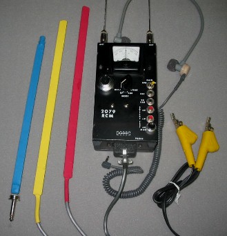 The 2079RCM locates many types of radio controlled, magnetically activated and current or voltage activated improvised explosive devices (IEDs). The unit contains a passive near-field detector for locating various types of radio controlled improvised explosive devices (RCIEDs), a Hall effect magnetic field detector for locating magnetic door switches and the magnetic field around relays and an extremely sensitive micro-ammeter for sensing current flow through a single wire. OPERATION: Set the MODE selector on MAG and press the +9MAG and then the +9 test buttons for 3 to 5 seconds . A steady reading from 400 to 500 to the right of center indicates satisfactory battery condition for those supplies. Press the -9 test button for 3 to 5 seconds and a reading from 400 to 500 to the left of center indicates satisfactory battery condition for that supply. Return the MODE switch to OFF. The radio frequency mode detects local oscillator radiation from many, but not all, receivers. Fasten the two antennas to the BNC right angle connectors on the 1"X1"X2" detector assembly. Position the antennas so they are both parallel and perpendicular. Connect the 20 foot BNC to BNC cable between the detector assembly and the main unit. Turn the MODE switch to RF and ZERO the meter. Manipulate the antennas and detector assembly to the suspect device. When an RF source is detected the meter will move to the right or left depending on the direction of the source. Remove the detector assembly and antennas when not in use and store them in the case. To test for magnetically activated devices, insert the RED magnetic field probe into the 20 foot extension cable and the cable into the main unit. Place the MODE selector in the MAG position and ZERO the meter. Pass the end of the magnetic probe over the word MAGNET on the front of the unit. Both visual and aural indication will be obtained. Pass the probe over the suspect device. If a magnetic field exists, the 2079RCM will find it. The magnetic probe will detect magnetic door switches and the on/off state of a relay. Switch to the YELLOW probe if the magnetic field is too intense to locate with the RED probe. The current probe detects minute amounts of current flowing through a single wire. Clip the "teeth" of the YELLOW alligator clips onto the wire two to three inches apart from each another. Turn the MODE switch to CUR and ZERO the meter. Use an explosive or remote wire cutter to sever the wire and observe the current flow. If the wire is longer than one foot, place the alligator clips as far apart as possible. In this application it is NOT necessary to cut the wire to view current flow. The current probe can measure up to 1 ampere. The 2079RCM contains a logarithmic amplifier. The meter is most sensitive when at or near the center and the sensitivity decreases as the pointer moves upscale. THE 2079RCM CONSISTS OF:
8/09 |
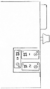 BATTERY REMOVAL INSTRUCTIONS:
Place unitmeter down on
BATTERY REMOVAL INSTRUCTIONS:
Place unitmeter down on