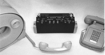
CONTENTS OF 7080 SYSTEM
1 7080 CONSOLE
2 CONSOLE TO TELEPHONE CONNECTING CABLES
1 RED TELEPHONE (COMMAND) WITH TALK/MONITOR SWITCH
1 BLACK TELEPHONE (BARRICADE)
1 AUDIO AMPLIFIER/SPEAKER
1 20 FOOT EXTENSION CABLE FOR CONSOLE TO AUDIO AMPLIFIER
1 BOX WIRE SPLICES
1 SPLICE CRIMPER
1 INTERCONNECT BLOCK
1 100 FOOT ROLL OF 4 WIRE CABLE
1 PELICAN WATERTIGHT CARRYING CASE
1 900 FOOT RETRIEVABLE CABLE AND REEL FOR BLACK TELEPHONE
1 PELICAN WATERTIGHT CASE FOR THROWING BLACK TELEPHONE
1 900 FOOT RETRIEVABLE CABLE AND REEL WITH THROW HANDSET
OPERATING THE 7080:
Referring to FIGs 1, 2 and 3 will greatly assist in understanding the various uses of the 7080.
FIG 1 covers situations where only the telephone handset is sent into the barricade area.
FIG 2 covers situations where the entire telephone is sent into the barricade area.
FIG 3 covers situations where a telephone already in the barricade area is used.
In all three cases the 7080 console can be connected to an outside telephone line if desired.
REMEMBER....THIS UNIT IS BATTERY OPERATED. ALWAYS MAKE SURE THE TWO RED POWER INDICATORS ARE OFF WHEN STORING.
Remove the console from the carrying case and place on a secure surface with the controls facing up. All six (6) switches in the front row should be in the forward (facing the negotiator) position. The RED PHONE TO BLACK PHONE switch should be in the OFF (right) position and the INTERNAL BATTERY switch should also be in the OFF (left/unmarked) position.
Select the operating scenario desired. Connect the wires and telephones as shown in that figure.
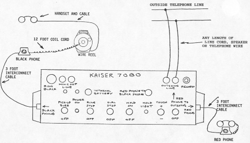 FIG 1. Assuming the unit is connected to an outgoing telephone line the negotiator may either communicate with the barricade area or connect the RED telephone to the outgoing line and make calls. To make an outgoing call place the RED PHONE TO BLACK PHONE switch in the OFF (right) position and the RED PHONE TO OUTGOING switch ON (up). A dial tone will now be heard on the RED telephone. Make a call if desired. If the negotiator wishes to allow the barricade to hear the call, place the RED PHONE TO BLACK PHONE switch ON (left). NOTE: When connected to an outside line the negotiator may, depending on the battery polarity of the 7080, notice a decrease in the level of audio heard from the telephone. Reverse the polarity of the system by placing the TOUCH +/- switch in the opposite position.
If the negotiator does not wish the barricade to hear the call but wishes to place the called party on hold, place the HOLD ON switch in the up position and the RED PHONE TO OUTGOING switch to OFF (down). The red HOLD LIGHT will now flash. The RED telephone can now communicate with the barricade if desired. If the barricade wishes to communicate with the outgoing line in "privacy" place both the RED PHONE TO BLACK PHONE and RED PHONE TO OUTGOING to ON and place the switch on the RED telephone instrument in the MON (monitor) position.
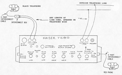 FIG 2. Wire the system as shown in the drawing using the connector block. Operate the 7080 as described in FIG 1 however to "ring" the BLACK telephone press the RING BLACK button for a moment. To determine if the BLACK telephone has answered the ring, place the PICK-UP BUZZ switch in the UP position. Once communications has been established return that switch to the OFF position. As in FIG 1, the RED telephone can communicate with the BLACK telephone or an outgoing line or both the RED and BLACK telephones can communicate with the outgoing line. To prevent the BLACK telephone from placing or receiving a call place the RING STOP and DIAL STOP switches in the UP position. These switches now control the outgoing line as negotiated with the barricade.
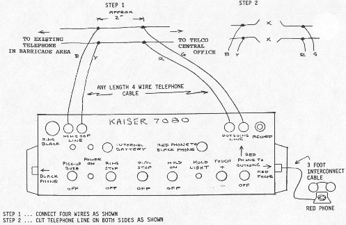 FIG 3. Connect the red/green and black/yellow wires to the telephone line going into the barricade area as shown in STEP 1 and STEP 2. Do not connect these wires to the 7080 until the following has been performed. Place the RED PHONE TO BLACK PHONE switch OFF. Turn the RED PHONE TO OUTGOING switch to ON. With the RED telephone switch in the TALK position listen to the RED telephone while connecting the red/green wires to the red OUTGOING LINE terminals. A dial tone should be heard. If a dial tone is not heard then the wires connected to the outgoing line are reversed. Remove the red/green wires from the red terminals and connect the black/yellow wires to the red terminals. A dial tone should then be heard. Assuming the wires are now correctly connected to the red terminals then connect the remaining pair to the black NON-COOP LINE terminals. Place the PICK-UP BUZZ in the ON position and press the RING BLACK button to call the barricade telephone. After communication has been established, operate the system as described in FIG 1 or FIG 2. If the telephone in the barricade area is a rotary dial type the DIAL STOP switch may be used as above. If, however, the telephone is a touch-tone type the following applies. If the touch-tone telephone is of an older variety, dialing may be stopped by reversing the polarity of the line with the TOUCH +/- switch. If the touch-tone telephone is of the newer variety reversing the line will accomplish nothing. To stop the barricade from attempting to make an outgoing call while connected to the outgoing line, disconnect the barricade telephone by placing the RED PHONE TO BLACK PHONE switch in the OFF position.
The RECORD jack contains line level audio with an impedance of 2,000 ohms. If the communication is to be monitored by an additional party a 2,000 ohm headset may be inserted into this jack. If the communication is to be recorded, this jack should be connected to the AUX or AUXILIARY jack on the recorder. If such a jack does not exist on the recorder, a 100 to 1 attenuator cable must be used. 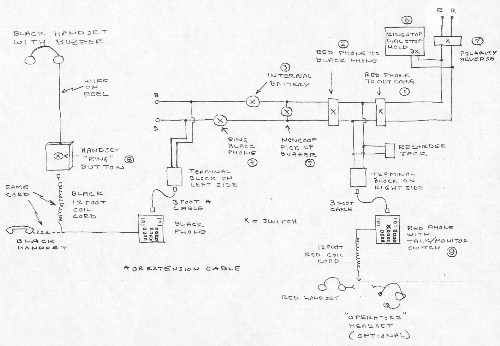
SYSTEM DIAGRAM
REMEMBER....THIS UNIT IS BATTERY OPERATED. MAKE SURE THE TWO RED LIGHTS ARE OFF WHEN STORING. WHEN STORING THE UNIT FOR LONG PERIODS OF TIME, REMOVE THE BATTERIES FROM THE HOLDERS.
As always, Alkaline batteries are preferred.
3/98
BACK TO SITEMAP BACK TO PRODUCTS HOME |
