RAS-515A
RASTER ANALYSIS SYSTEM
RAS-515A
RASTER ANALYSIS SYSTEM
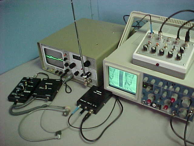
| The RAS-515A permits viewing of a wide variety of signals such as video, digital, sub-carrier, pulse, etc. Although other spectrum analyzers may be used, the unit is designed for use with the Avcom PSA 65x series. In addition to the Avcom and RAS- 515A, a VM515 baseband video demodulator and oscilloscope with Z axis input are required. |
INPUT REQUIREMENTS:
Detected baseband video from Spectrum Analyzer or receiver with up to 5 MHz band width. 1 volt P/P nominal. Optional external vertical sync.
OUTPUTS:
30 V P/P video. Vertical sawtooth at 1 V P/P. Horizontal Sync.
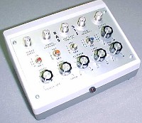
CONTROLS:
POWER:
CONNECTORS:
Apply the baseband video signal to the oscilloscope "A" channel vertical input. Adjust the horizontal sweep so two or three segments of the composite video signal remain stationary. Note the polarity of the sync signal and place the SYNC POS/NEG switch in that position. Move the cable from the oscilloscope vertical "A" input to the RAS-515A VIDEO INPUT. Connect a cable from the HORIZ SYNC OUT to the horizontal sync input of the oscilloscope. Connect a cable from the VIDEO OUTPUT to the oscilloscope Z axis input. Connect a cable from the VERT SAW OUT to the oscilloscope "A" channel input. Apply power to all units. Adjust the horizontal sweep so four or five segments of the vertical sawtooth are visible. Adjust the oscilloscope and VERT AMP control for a full scale image. Adjust both the horizontal sweep and VERT FREQ until a picture appears. Adjust the VERT SYNC, CLIPPER LEVEL and SYNC ROLL OFF controls for a stable picture.
Tune to an FM station with a known subcarrier (Musak). Adjust controls until a series of light and dark lines appear on the oscilloscope. The VERT FREQ and oscilloscope sweep controls will determine the number of lines. The light and dark lines represent a coherent signal. This method is particularly useful for finding coherent modulation in noise masked signals. NOTE: There is no one setting for the controls. Tune to as many known signals as possible to develop proficiency.
The 1/4 inch jack on the rear panel permits viewing of telephone line level audio signals. A special 1/4 inch plug to telephone plug cable is provided for that purpose. The AC input impedance is 600 ohms. To view audio from a recorder or receiver it is necessary to match this jack with a 8 ohm to 1K ohm transformer (not supplied).
VIDEO GAIN, SYNC ROLL OFF, CLIPPER LEVEL, VERTICAL FREQUENCY, VERTICAL AMPLITUDE, VERTICAL SYNC SOURCE, 75 OHM TERMINATION IN/OUT, VIDEO POLARITY AND SYNC POLARITY.
90 to 260 VAC/47 to 63 Hz.
VIDEO INPUT... from 1V P/P video source
HORIZONTAL SYNC OUT... to oscilloscope sync input
EXT VERT SYNC IN... from external sync generator (Optional)
VERT SAW OUT... to vertical input of oscilloscope
VIDEO OUTPUT... 30V P/P to Z axis of oscilloscope
9/00